JCATI CARBON FIBER RECYCLER
Construction
The video to the right is a time-lapse of machining the bearing blocks for the crusher housing. The video shows the many steps required per hole: center drill, drill, chamfer, and threading. Using a Bridgeport vertical mill increased efficiency in manufacturing and accuracy in the parts.

Figure 9: Bearing Block Machining
Figure 11 demonstrates the method used to scribe the hole locations on the bearing blocks. The use of a flat plate and height gauge precisely located each hole on the bearing block allowing for quick setup on the vertical mill. The blue face is a die used to highlight the markings made by the height gauge

Figure 11: Bearing Block layout
The machine set up and stop shown to the right is how the bearing blocks were placed for machining. The stop placed at the the end meant that the holes would all be drilled in the same position. This also increased production as their was no measuring each time the block was placed.

Figure 12: Machining set stop
The image on the right shows the cutting process for the angle iron frame pieces. This particular cut leaves a 45-degree angle that allows for ease of assembly and welding. The aluminum block in the center is used to provide stability in the clamp during the cut.
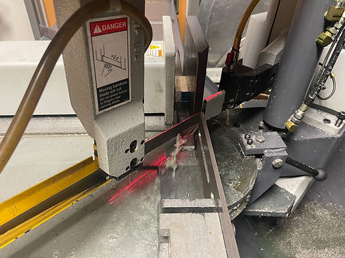
Figure 7: Angle Iron Cut
Figure 8 shows the 16' bar stock being cut to 30". The metal cutting disc chop saw was chosen as it could be carried to the location of the metal as the piece is quite heavy. The 30" piece could then be moved to the machine show were the bearing blocks were to be cut.

Figure 8: Bar Stock Cut to Length
Figure 10 to the right is of the guide bar set up for the handheld plasma cutter. The choice to cut the plates with the hand torch was chosen as the CNC Plasma had accuracy issues. The bar in the picture is used to guide the plasma torch in a straight line to get a consistent linear cut.
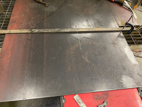
Figure 10: Plasma Cutting Plates
The template to the right is a fixture piece used for cutting the holes in the housing plates. Each hole was oversized by 5/8 of an inch to make sure the center of the cutter was at the edge of each hole. This allowed for quick and easy cuts while maintaining precision in the location.
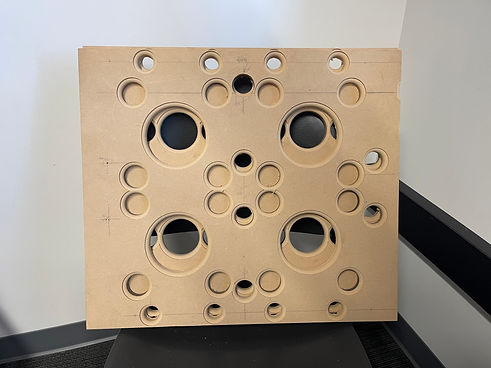
Figure 13: Plasma cutter guide
Figure 14: Drawing Tree

Construction Updates:
To date, the project's part construction has been completed and assembled. This requires the use of the hydraulic band saw to produce clean accurate cuts for the assembly of the pieces. In addition to the band saw, the vertical mill was used to drill, chamfer, and tap the bearing block holes, along with the top plate. This was the most efficient way to perform the task, as the mill has a vice and stops to place each part in the same location every time to drill each hole. After this construction occurred, the housing plates were cut using a template to guide the plasma cutter by hand. The hand-held plasma was chosen as the CNC Plasma was malfunctioning. Lastly, the frame has been welded together to allow for mounting of the Housing plates and bearing blocks.